
.jpg) By: Ernesto Wiedenbrüg, Baker Instrument Company, an SKF Group Company
By: Ernesto Wiedenbrüg, Baker Instrument Company, an SKF Group CompanyIntroduction:
Gone are the days when a MegOhm meter and a digital multi-meter were the main tools in electrical maintenance. Advances in technology now offer engineering professionals both off-line and on-line (real time) instruments to verify the health of rotating machinery.
Modern on-line technologies permit assessment of the ‘whole motor system’, which is comprised of three components: power, motor & load. By focusing on these three components, troubleshooting now becomes truly predictive!
Problem Assessment:
Maintenance professionals agree that excessive heat causes rapid deterioration of the winding insulation in motors. NEMA guidelines on voltage quality are complemented by automated load estimation techniques and have become a useful tool for evaluating the thermal stress on a motor. Accurate load assessment is possible using modern motor theory. This allows monitoring from the motor’s electrical terminals using only the current and voltage signals. This load monitoring technique displays accurate steady state speed and operating torque, plus more importantly, the instantaneous torque present on the shaft. This information is invaluable when trying to discern between anomalies caused by mechanical versus electrical problems.
Power Condition:
Induction motors are designed to operate at rated, balanced and undistorted voltage conditions. In reality, this type of power condition is rare. Clearly, lowering the load level below 100% load can solve the added heat of operation due to a poor voltage condition. The question of how much the load has to be lowered (derated) is answered by NEMA’s MG-1 and MG-2.
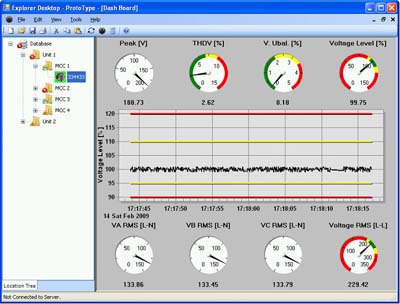
Figure 1 shows the NEMA derating curve for percentage of unbalance.
This graph’s x-axis is defined in the following formula:
The use of the derating curve is best described as the higher the level of unbalance, the lower the acceptable level of steady state load. For example: if you have a 100 hp motor and an unbalance factor of 3%, you would need to derate the motor to 0.9 or 90% of capacity, or 90 hp.
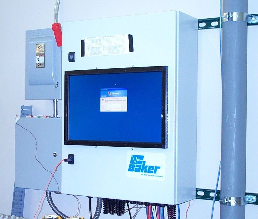 Figure 2
With poor power condition and the use of VFD’s, proper derating is highly important. Figure 2 shows the voltage that a VFD running at almost a 6-pulse mode will send to the motor. The distorted currents are the motors reaction to the poor power condition. This scenario shows a NEMA derating of 0.7 or 70% of rated output. If run higher than this, it creates thermally an equivalent to an overload situation, which leads to excessive heat.
Heat within a Motor:
It is known that excessive heat will cause rapid deterioration of the winding insulation in electric motors. The common rule states, for every 10°C additional heat to the windings, the life of the insulation is reduced by half. For example, a motor that would normally last 20 years in regular service is running 40?C above rated temperature. Under these conditions, the motor would have 1/16 or about one year of useable life. Many articles and studies have been done that agree with this general rule. Leading standard’s organizations have come to the conclusion that 30% of motor failures are contributed to insulation failure and of these, 60% are overwhelmingly caused by overheating.
Modern on-line technology evaluates these processes to find the root causes to these problems. Predictive maintenance professionals are more and more correcting potentially damaging process problems prior to motor insulation deterioration, which can lead to high rectification costs and business downtime.
In an example taken from a coal-fired power plant in the United States, a 7000 hp 6.6kV motor was running with only 7% over current, but additionally with an 8% over voltage. Two identical applications had previously undergone unscheduled outages within the last 12 months. Looking at the stator current of this motor, a mild overload had been identified. It was only after looking at the true load to the motor (with on-line test equipment), that an overload of nearly 20% was discovered. This explains why these motors were failing at a rapid rate. The repair for each of these motors ran into the hundreds of thousands of dollars. This example brings home the point that the common measure of load estimation, current level, is extremely unreliable in a modern high-load high-uptime environment.
Effective Service Factor:
Another highly important element in electric motor maintenance is the understanding of the Effective Service Factor concept. Whilst poor voltages raise the motor’s operating temperature, low load levels will lower them. The measure of acceptability of any particular voltage quality and percentage load combination is the assessment of Effective Service Factor. This relies heavily upon the high accuracy of the load estimation. Bringing voltage and current levels, along with accurately estimated output power to the field is no easy task. This can be obtained by applying motor science, and modern DSP algorithms only to currents and voltages. In the past, less accurate methods led to poor assessments. Voltage conditions which lack optimal level, balance or a richness in distortion are typical examples of common voltage conditions that cause excessive heat to the motor.
The formula for calculating effective service factor is:
This concept can be easily understood. The professional organization, NEMA, specifies the maximal load at to which the motor should be run, granted that it has to deal with a particular low voltage quality. If the division of %Load by %NEMA Derating results in a value larger than 1, then the %Load level being operated is higher than the NEMA standard allows, pointing to a probable overheating mode of operation for the motor. For example, if we use the same 100 hp motor with the 3 percent derating factor and a %Load of 95 percent the Effective Service Factor would be:
The key benefit to Effective Service Factor is the combination of professional standards and real life applications, offering predictive maintenance professionals a solid conclusion. If the Effective Service Factor is greater than 1 the motor needs further investigation to determine the severity of the potential problem.
New Technology Offers Greater Flexibility:
Baker/SKF understands the need to reduce costs and maximize electrical equipment reliability and productivity. The latest project from Baker/SKF is the SKF On-Line Motor Analysis System NetEP and iNetEP. This advanced monitoring instrument offers real time data on plant operations and efficiencies. This changes the rules of machine maintenance. Typically, maintenance professions do one of two things: wait for equipment to break or they shut equipment down on a preventative schedule for periodic testing.
The NetEP or iNetEP offers a third alternative. That of monitor rotating machinery continuously from the convenience of an office or central control room or anywhere an Internet connection is present.
This enables the engineer to break away from time consuming, route based, data gathering tools and obtain multiple critical machine status updates upon request as well as receive alarm notifications as soon as they happen. As well as understand the true condition of equipment running by obtaining pertinent information on the motor driven load and incoming power.
Reduce Maintenance Costs:
Routine maintenance is a must for industrial plant operations. Buy why take equipment out of service if it is not necessary? These new online systems monitor and track over 100 parameters from up to 32 motors on 7 voltage busses and can pin point specific problems spots to focus further maintenance activities. This reduces the cost of general maintenance and the cost of training personnel charged with performing these activities.
Increase Serviceable Life:
The predictive nature of the NetEP and iNetEP instruments allow the user to extend the working life of rotating instrumentation by providing the information needed to prevent unnecessary wear by optimizing motor and process control conditions. This helps to avoid the domino effect of component failure.
Conclusion:
Over time the increasing complexity of rotating machines has pushed the need for predictive maintenance instrumentation to successfully determine root cause analysis of motor failure or stress. The use of sophisticated drives such as VFD’s has also created a need for equipment to evaluate and monitor the variable frequencies and voltage levels transparently. These needs are being met by modern on-line testing equipment designed to evaluate and determine problems prior to catastrophic failure.
Bearing and winding failures are the most common motor failures. Of these failures, 60% of winding failures are subject to heat related issues. These failures contribute to hundreds of thousands of dollars in unscheduled downtime annually. On-line motor monitoring allows analysis of the process, enabling the user to verify and identify problems prior to motor damage.
Until now Effective Service Factor has been widely misunderstood. This highly important concept relies heavily on the high accuracy of the load estimation with past procedures being less than accurate. Without this concept, many heat related issues go unchecked causing motors to develop problems.
The more capable instrumentation becomes, the more suitable predictive maintenance becomes for plant managers. This represents good news for business, since electrical on-line monitoring technology has successfully integrated it into a comprehensive testing and monitoring scheme. Newly developed technology surpasses the predictive maintenance professional expectations in offering an understanding of diagnostic problems associated with this type of system. In fact this type of testing equipment has become a necessity in completing the predictive maintenance professional’s tool belt.
References
NEMA Standards Publication No. MG 1-1993, Motors and Generators, National Electrical Manufacturers Association, Washington, DC
By: Ernesto Wiedenbrüg, Baker Instrument Company, an SKF Group Company
About the Author:
Ernesto Wiedenbrüg obtained his Masters equivalent from Aachen, Germany, and his Ph.D. from Oregon State University in electrical engineering, focusing on power and electrical machines. During his education he worked for Siemens Argentina, as a Research Assistant in Germany and as a Power Engineer in South Africa. His doctorate was partially funded through a fellowship from Volkswagen, and by teaching electrical machines at Oregon State University. He was the general manager of the EPRI and BPA funded Motor and Drive testing Laboratory MSRF. He is currently working as a project engineer for Baker Instrument Company, an SKF Group Company.
Sales, service and support for Baker condition monitoring equipment is undertaken by UK agents, Whitelegg Machines Ltd.
Mr Michael Herring
Whitelegg Machines Ltd
19 Crompton Way
Manor Royal
CRAWLEY
RH10 9QR
Tel: +44 (0) 1293 526230
Email: This email address is being protected from spambots. You need JavaScript enabled to view it. www.whitelegg.com
Editorial contact Gavin Sandeman 07879 681136
